Table of Contents
Open Table of Contents
context
i wanted to learn how to build a robot without the headache of designing one from scratch, so i bought this simple desk buddy robot kit from taobao.
the parts:

and the assembly tutorial is from huy vector
it took me roughly 3 days to build the robot, and another week to write about the process because procrastination got the better of me.
chassis assembly
using copper wire to build a chassis was new to me, and it was part of the reason why i picked it up, showing me i could use simple materials to make a chassis without a 3d printer.
these are the two types the copper wires used to construct the chassis:
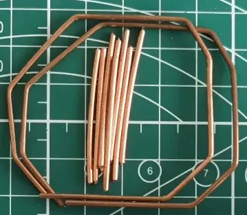
- big octagon as the frame
- small wires as joints
based on the tutorial video, everything looked so simple. to assemble the chassis, i just needed to “weld” the joints by:
- tinning my solder tip
- apply flux on the joints and the octagon
- dip the molten solder on the joints to “weld” the octagon and join
- repeat till both joints and octagons are “welded” and i’ll end up with a nice chassis!
I WAS WRONG, it wasn’t as easy as the video made it out to be. this was one of the most frustrating thing to build out of the entire kit. i took 70% of the time working on the chassis because:
- the joints are bent
- i needed to figure out how to properly position the joint and the octagon point without it falling
initially, i decided to ignore it because well the bent is ever so small. it shouldn’t affect much right?…
WRONG, my oversight resulted in a chassis with bent and misaligned joints. it looked like quite distorted, i wasn’t sure if there was even enough space to put the other components and align the motors
so i decided to:
- dismantle the chassis
- remove the excess solder on the copper wires
- straighten the bent joints
- re-assemble the chassis
the whole process took me two hours, but it was well worth it. this is how it looked like afterwards.
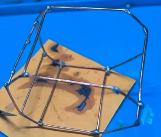
i had to add a few more joints afterwards, and it was ready for the motors to be placed!
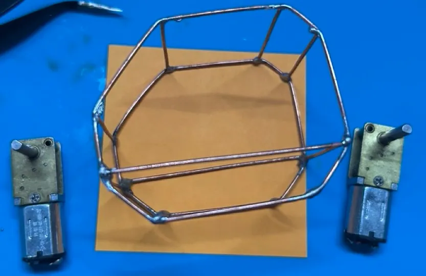
motor crisis
in my head i was like “yes!”, the frame is done it’s just the motor now but thinking “just” the motors, set me up for a whole level of frustration as i had troubles trying to attach the motor to the chassis.
the solder wire i had didn’t want to bond with the bronze portion of the motor and the copper wire. i tried so many different ways including using wires and rope to attach it
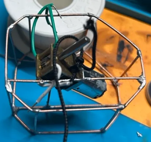
it looks like crap and doesn’t work, so i had to think of another way.
then i recalled i had another spool of solder wire lying around, it was a 99.3% tin solder virtually lead free. so i decided to try it out and hoped for the best, because if it didn’t work i’d have to abandon ship.
but thankfully, it worked!
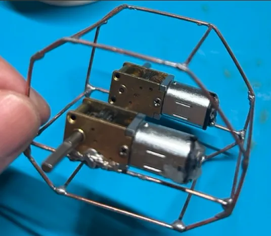
i’ve got some ideas as to why, it could be the composite of the solder wire.
i was using a cheap 60/40 i got from my hardware store, while the other was a 99.3% tin solder wire i got from taobao. maybe the higher tin content helped better bond the bronze to the chassis.
however, i didn’t dwell too much on it as i was relieved the motors are attached and i can move on to the attaching the electrical components
le components
there are a few components to make the whole thing work:
- oled screen - displays the eyes
- esp32 c3 mini - the brain of the build
- mini L298N - talks to the two motors and the esp32
there are the battery, usb charger and switch but i didn’t include them because it wasn’t required to get the whole thing running
there was a wiring diagram for me follow:
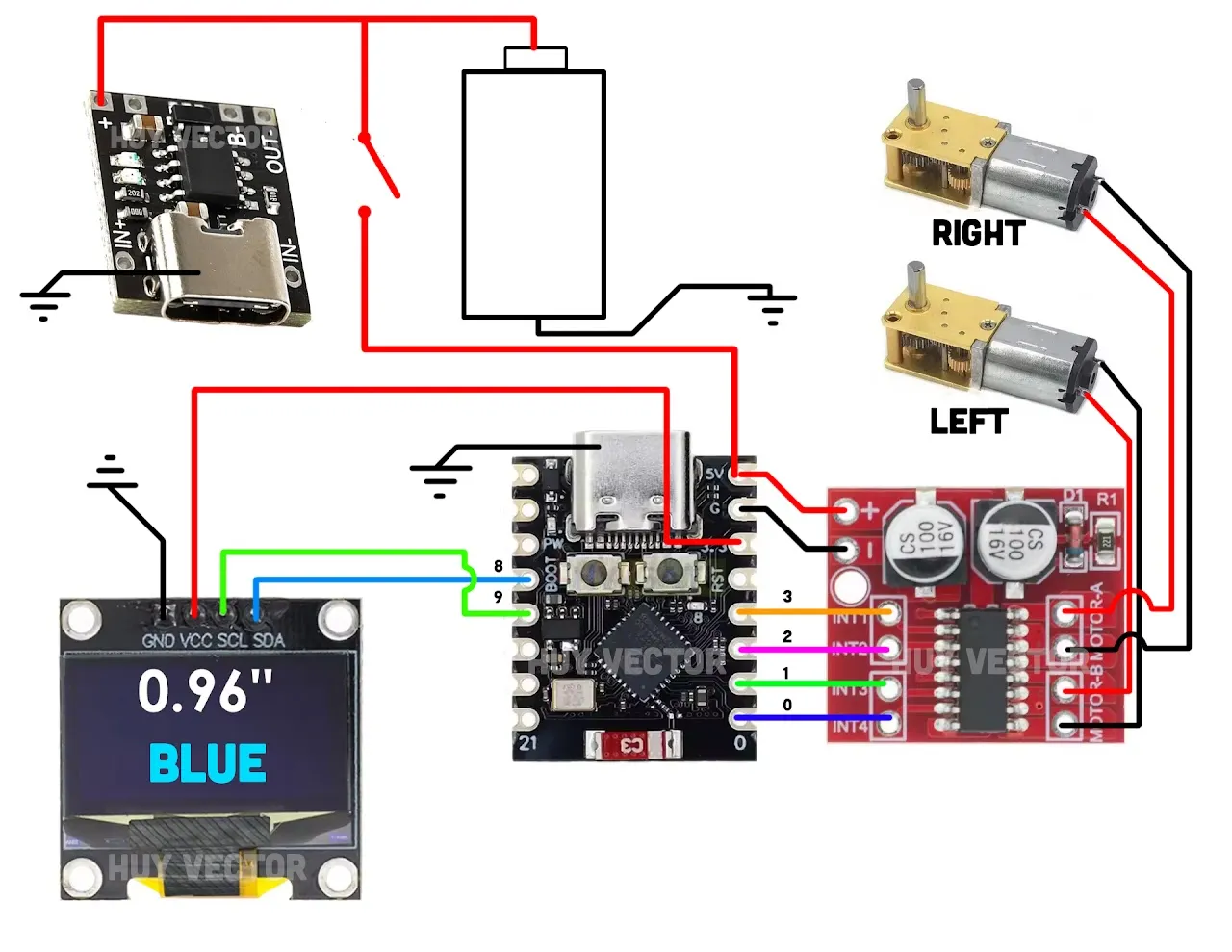
but the process of connecting them was a long and interesting process. why?
i didn’t have cables on hand, so i had to use the copper wires it came with. there aren’t any insulation on it so i needed to:
- figure out how to bend the wires to prevent it from touching as it can create a short
- get creative with trying to keep the wires in the through-holes while applying flux and solder WITHOUT using my hands to stabalise the wire
- not burning the board because its so tiny
through this process, i lost count of the number of times i’ve scalded my fingers. AHHHH
esp32 and oled screen
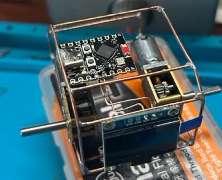 the screen was attached to the front of the chassis with super glue applied to its four corners
the esp32 was attached with solder on the usb port to the chassis.
the screen was attached to the front of the chassis with super glue applied to its four corners
the esp32 was attached with solder on the usb port to the chassis.
then, i spent some time trying to bend and guide the wire to my desired through holes. i.e (oled SDA pin to esp32 pin 9).
esp32, mini L298N and the two motors
with the esp32 in place, i can move on to the motor controller (mini L298N) and the two motors.
this was quite straightforward because the components are quite close to each other
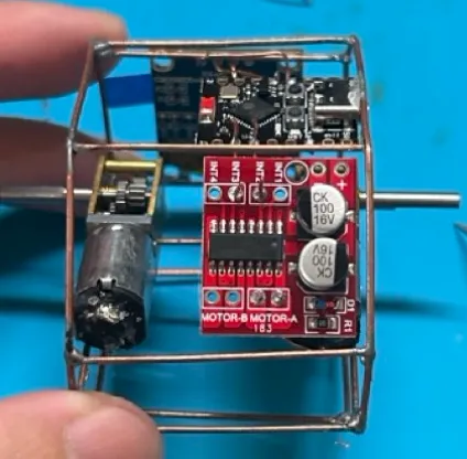
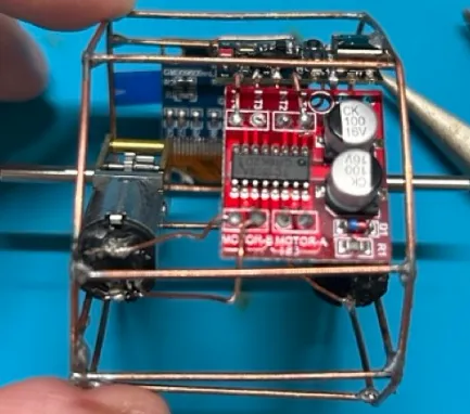
- i gave up trying to make the wire look nice for the two motors
with this done, all the electrical components are in place!
the final stretch
with my heart racing and being anxious due to my wiring work, i powered on the esp32 with a usb c cable from my laptop!
remember to use a usb-c cable that can carry both data and power. not just power!
it turned on! but i was left confused and thinking is this whole thing busted? the board was showing a red LED, only one side of the motor was spinning and the screen wasn’t showing anything.
troubleshooting time
STAY CALM! i must’ve messed it up somewhere. i took stock of the issues occuring and prioritised which one to tackle first.
despite the red LED and one motor running, i knew that the software is flashed onto the board. if not the motor wouldn’t even move.
after thinking about it, this was the priority knowing that the software is flashed
- the screen - eyes should show up
- the other motor - it should spin as well
- the red led - there should be a secondary led and the motors shouldn’t be constantly spinning
the screen
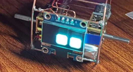
i took a look again at the video and i realised i missed out the GND pin! all four pins had to be filled and the component has to be grounded before it can boot.
so i took a small piece of wire and solder the GND pin to the frame and it worked!
the motors
the motors was a trip, it was coated with a layer of goo to protect it from factory dust. but it covered up the two connectors, so i had to:
- remove the goo buildup
- melt the existing solder on the connector
- use a tweezer to press the copper wire down into the connector, to ensure the solder was in its molten state it would stay in that position so that when it dried it’ll stay there.
i charred the plastic around the motor, but that was fine because both motors are running after it was plugged in!
the firmware
lastly, the firmware. it was really sus that the motor was constantly running when it should only spin between intervals (i.e. every 5s or 10s) and there was only the red led showing. usually red color only means bad.
so i googled and i came across this guide , i figured out that a secondary led should light up if everything is fine.
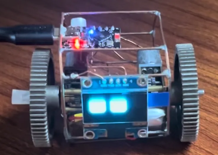
i got the code from the tutorial video and re uploaded the code to the esp32, it took a good 60s but luckily after i updated the code it works!
the screen is displaying with the eyes and the motor moves expectedly.
conclusion
building this was fun! the process of burning my hand, redoing the chassis, taking a closer look at the wiring diagram and figuring out why it didn’t work was engaging.
here’s a demo of it:
this build got me closer to:
- building a simple robot which involved motors, display and a microcontroller
- practicing soldering on a real kit rather than a perfboard with LEDS
- learning how to debug a physical device
it also revealed some gaps:
- not fully understanding the circuit diagram. (i was honestly just following the tutorial)
- don’t really know how to use a multimeter to test the component to see if it’s properly soldered
which i’ll be working on next! speaking of which, there’s also a line and self balancing robot which i’ll build and write about. but as to when it’ll be done, i’ll defer it to when the article comes out 😬
till next time!